

DFM and preliminary mould design for tool shops and moulders
From a STEP file Tool concept & feasibility in minutes
Feasio finds the opening direction and every undercut, proposes the mechanism (slide, lifter, wedge-actuated split core), checks draft, wall thickness, sink and the drawing’s tolerances, and writes the customer report and the toolmaker brief. You review and decide.
3 places · tool shops and moulders in Hungary first
- In
- STEP or IGES, material, annual quantity
- Out
- Customer report, internal edition and toolmaker brief, PPTX and PDF
- Works to
- SPI classes, VDI 3400, W.-Nr. steels, standard mould bases
- Report languages
- Hungarian and English
What a new part costs you before you win it
An RFQ arrives as a STEP file and a deadline. Before you can price the tool somebody has to decide how it opens, what traps the part, how many cavities, which press and which steels. In most shops that somebody is the best designer you have.
Senior hours spent on quotes you may lose
The concept work happens before the order exists. Every quote you lose was paid for in design time anyway.
The undercut found at T1
A snap hook or a back-drafted wall missed at the quote comes back as an extra slide, re-cut steel, another sample loop and a margin that has gone.
A price with no reasons behind it
When the customer sees only a number, they compare numbers. A quote that shows why the tool needs two lifters and a hot runner gives them something else to compare.
The first pass, moved from your designer's desk to Feasio
| Today | With Feasio | |
|---|---|---|
| Opening direction | Turned by eye in CAD, often in vehicle coordinates | Ranked from the part's own design axes, with what each direction traps and costs |
| Undercuts | Spotted by experience; some show up at T1 | Every trapped face mapped and grouped into named regions with release direction and travel |
| Mechanisms | Sketched from memory | The simplest release that works: lifters, slides, core pulls, V-lifter pairs, two-stage ejection, unscrewing cores, stripping |
| Draft, walls, sink | Checked where someone thinks to look | Every face against a four-tier draft policy; wall field, sink and hot cores located on the part |
| Gate, cavities, cycle | Rules of thumb in a spreadsheet | Gate on the parting line with hot-runner rules, cavity count, press size and a cycle range with its basis |
| What the customer gets | An email with a price | A report that opens with the verdict and the part changes they need to make, in Hungarian or English |
How it works
Three steps. Each result says what was measured, what was assumed and what is waiting for your decision.
Upload the part
STEP or IGES, the material and the annual quantity. Add cosmetic faces, faces where no gate may go and the texture if you have them. Anything you leave out is filled with a marked default.
Feasio does the first pass
Opening direction, draft, walls, sink and hot cores, undercuts and the mechanisms that release them, parting line and surface, gate and ejectors, tool interior, cavities and cycle time. Fast scans rank the options; exact CAD geometry confirms the chosen one.
You decide and send
Every decision arrives with a recommendation and the numbers behind it. Accept it or change it and the rest follows. Then export the customer report, the internal edition and the toolmaker brief.
What your engineer works in
The app follows the order a tool designer works in: part, direction, parting, tool interior, layout. Screens below are from the current version.
-
The part, read the way a toolmaker reads it
Ribs, bosses, snaps, holes, pockets and threads with their real pitch, counted and grouped in a CAD-style tree. Material and annual quantity sit next to the part, because they set the draft, the wall limits and the cavity count.
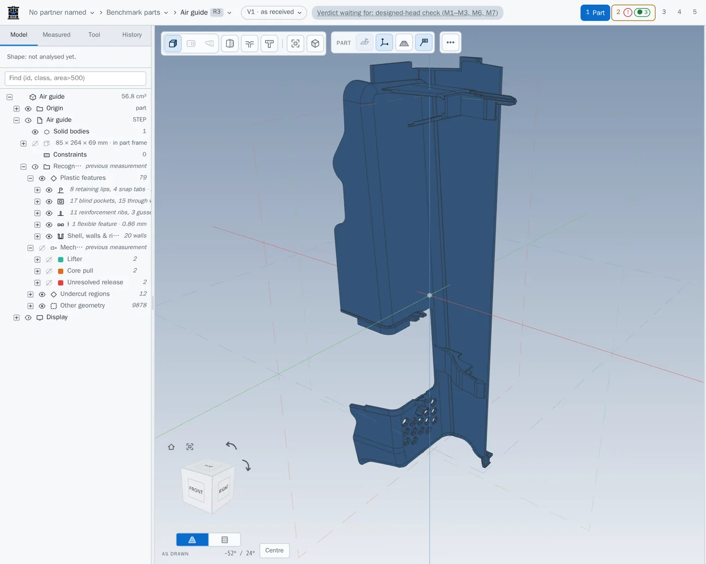
Part step: 79 plastic features found on an air guide, grouped by kind. -
Opening direction and what it traps
Feasio reads the part's design axes, so a part delivered in vehicle coordinates still opens along its designed axis. For the chosen direction it paints every trapped face and groups them into regions, each with a nominated release.
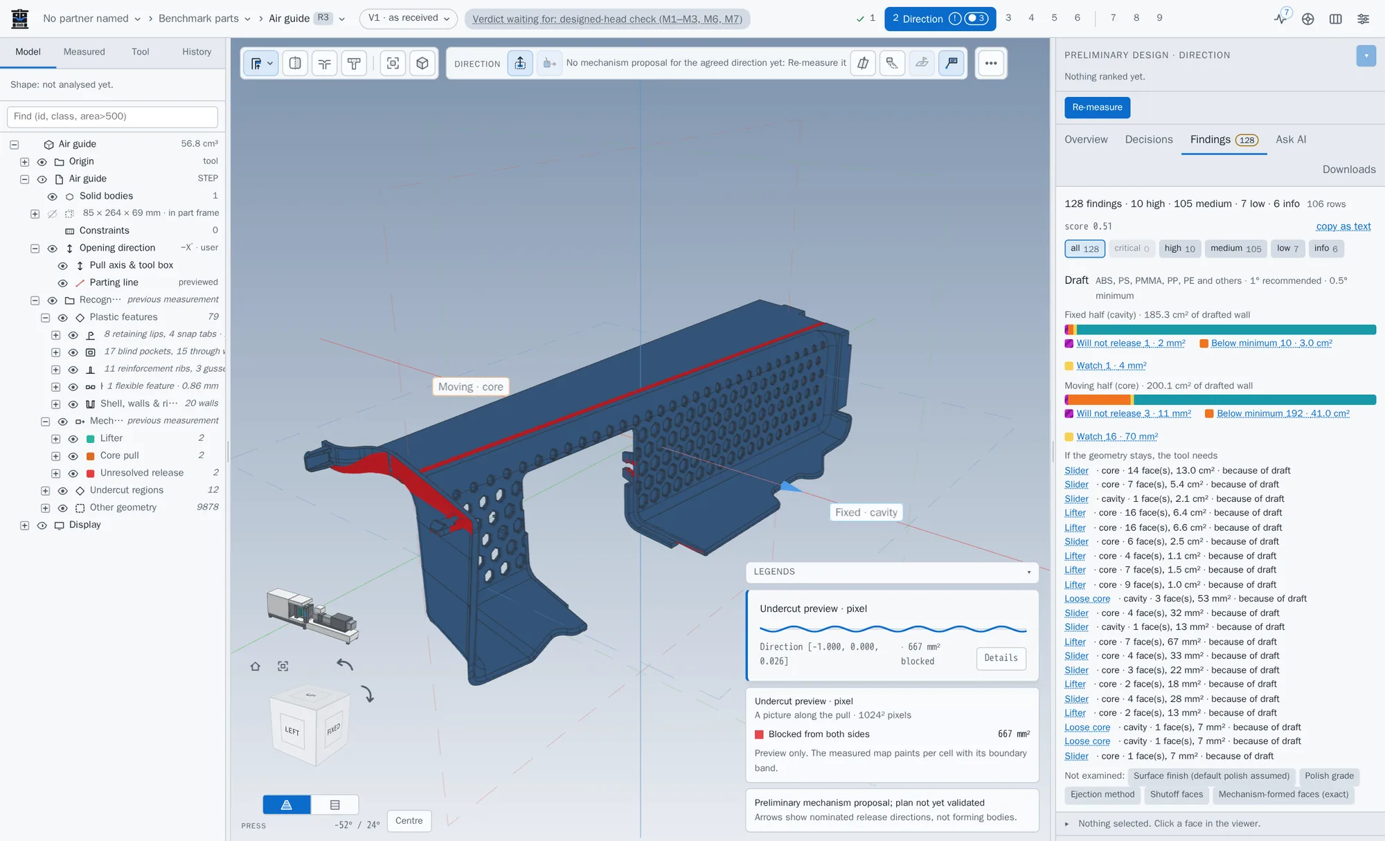
Direction step: surfaces blocked from both halves, in red. -
Decisions that arrive recommended
Each open question comes as a card: the calculation, the recommended answer, the alternatives and an AI reading of the same numbers. Repeated findings are grouped under one name with a count, so you answer a group once instead of face by face.
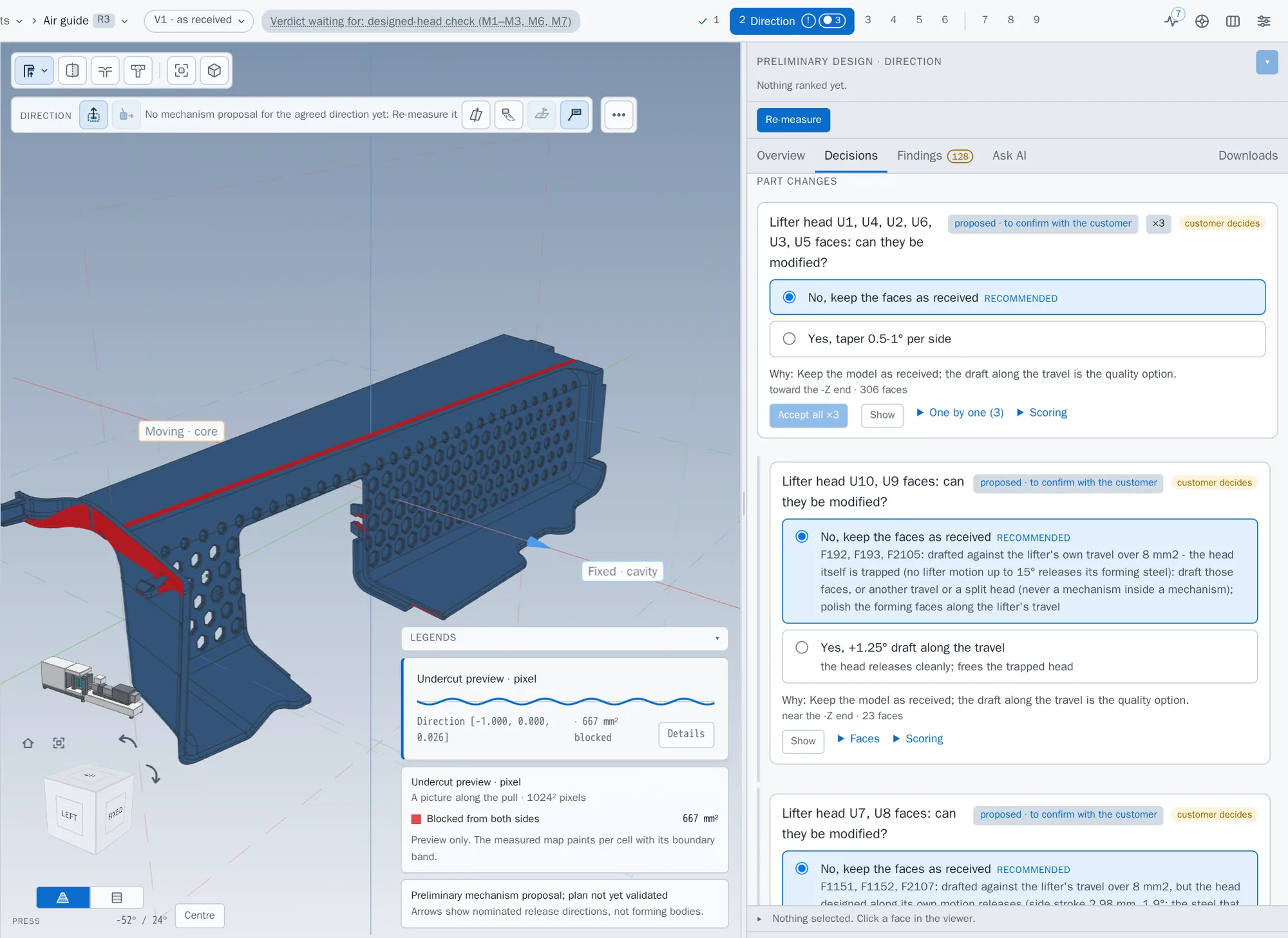
Decision cards: recommended answer, reason, and one click for a group of three. -
One board for where every part stands
The right rail shows each part's state: what is done, what is waiting for you and what is running now. Long computations show their progress and their measured time.
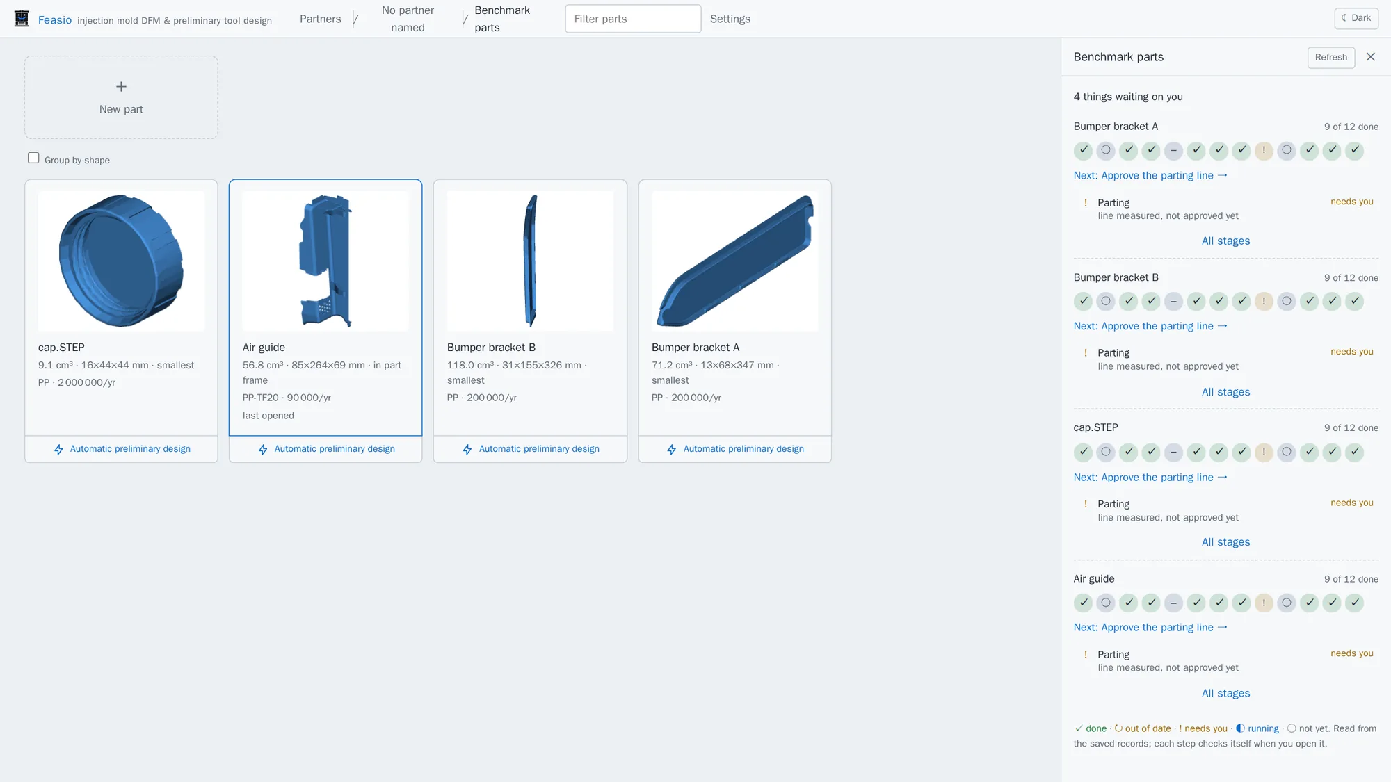
Project status board: what is done, and what needs you next, per part.
Everything you get from one STEP file
One pass, one record, one report. Each item below is in the product today.
- Opening direction ranked in the part's own design frame, with reasons and the cost of each candidate
- Draft check every face against a four-tier policy: material, side, depth and VDI 3400 texture
- Wall thickness a combined wall field; thin and thick spots located, uncertain values shown grey
- Sink and hot cores junctions against the material's limit, and where the plastic freezes last
- Undercut map trapped faces grouped into named regions with release direction and travel
- Mechanism concept lifters, slides, core pulls, V-lifter pairs, two-stage ejection, unscrewing cores and stripping, in toolmaker order
- Parting line and surface the silhouette line, its steps and the shut-off faces
- Gate and feed gate on the parting line, hot or cold runner by rule, ejector pins
- Programme cavity count, clamp force, press size and a cycle-time range with each term explained
- Tool interior inserts, mechanism heads and the opening sequence as a storyboard and an animation
- Tool specification SPI class, steels by W.-Nr. and hardness, envelope on standard mould-base sizes
- Material warnings flagged where the material and the geometry do not suit each other
- Reports customer and internal editions plus a 5–8 page toolmaker brief, in Hungarian or English
- Decision log every choice on record and carried over to the next part revision
The report your customer reads, and the brief your toolmaker builds from
Verdict first, then the evidence: one finding per page, the number in the title, assumptions in one place. Pages below are from real exports, not mock-ups.
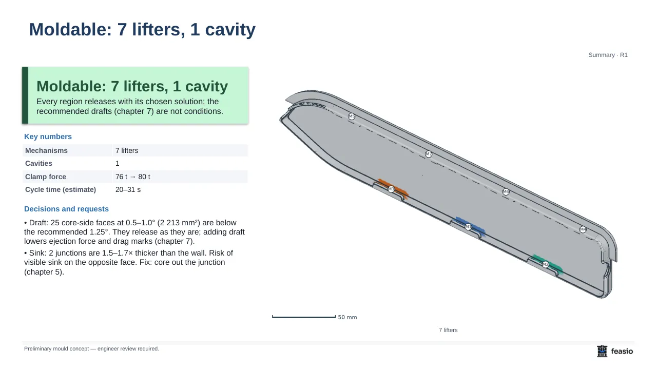
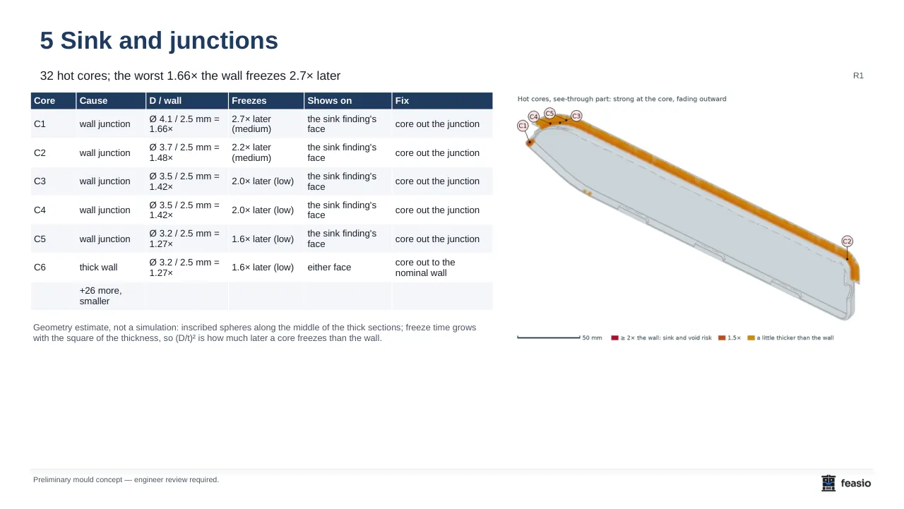
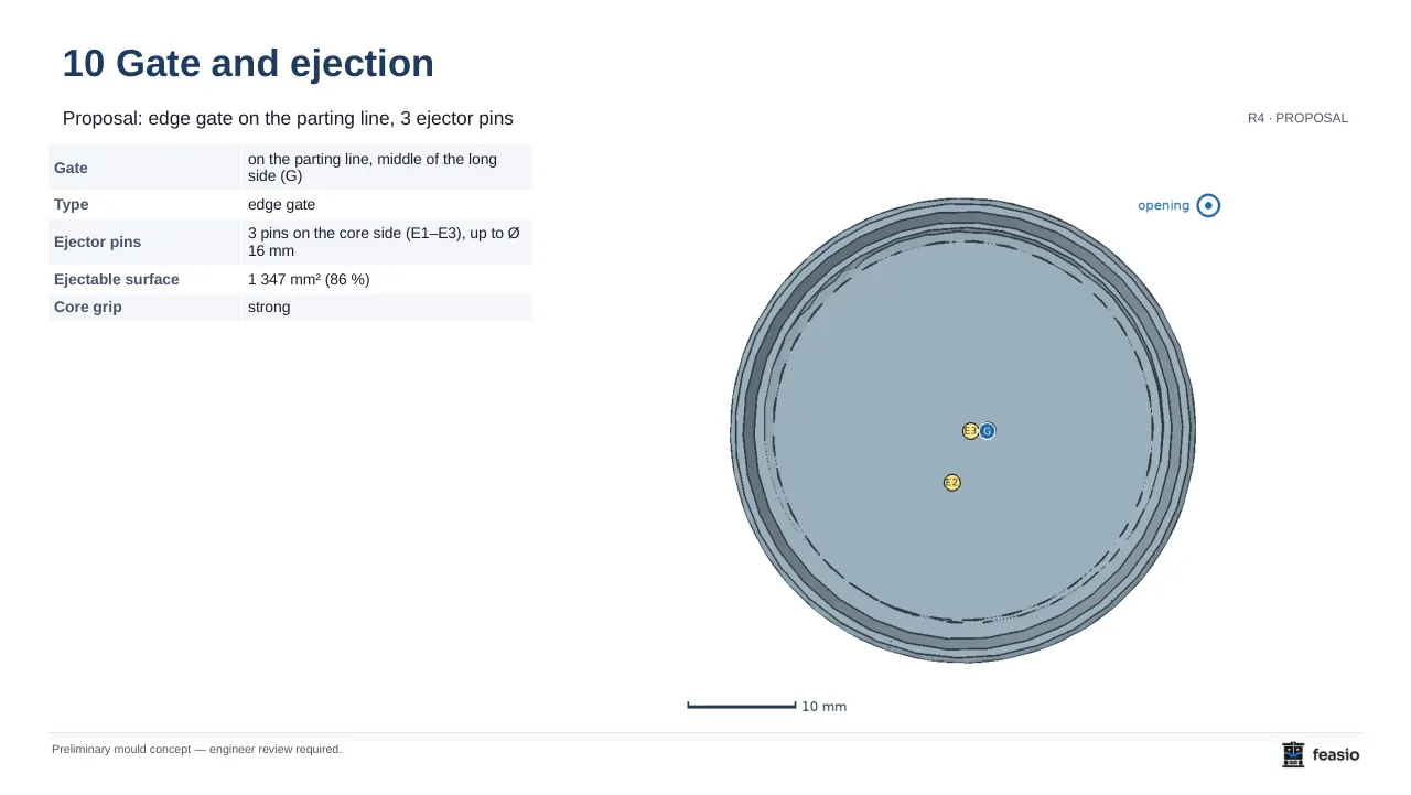
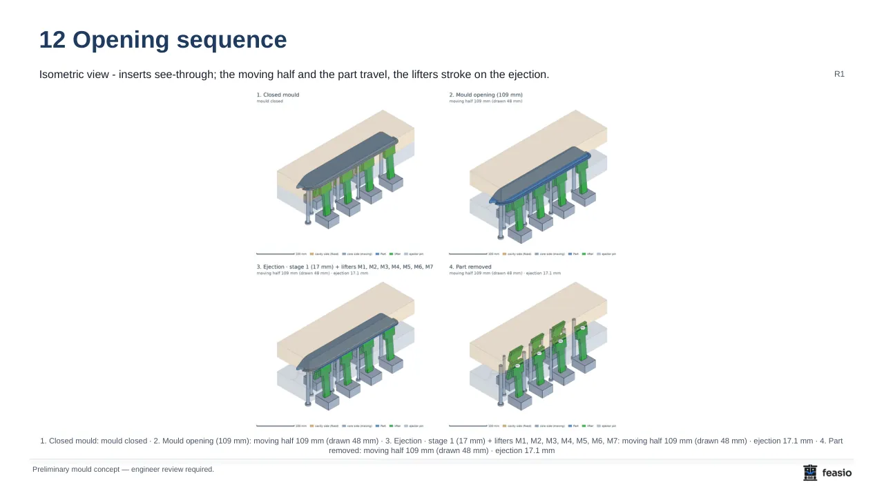
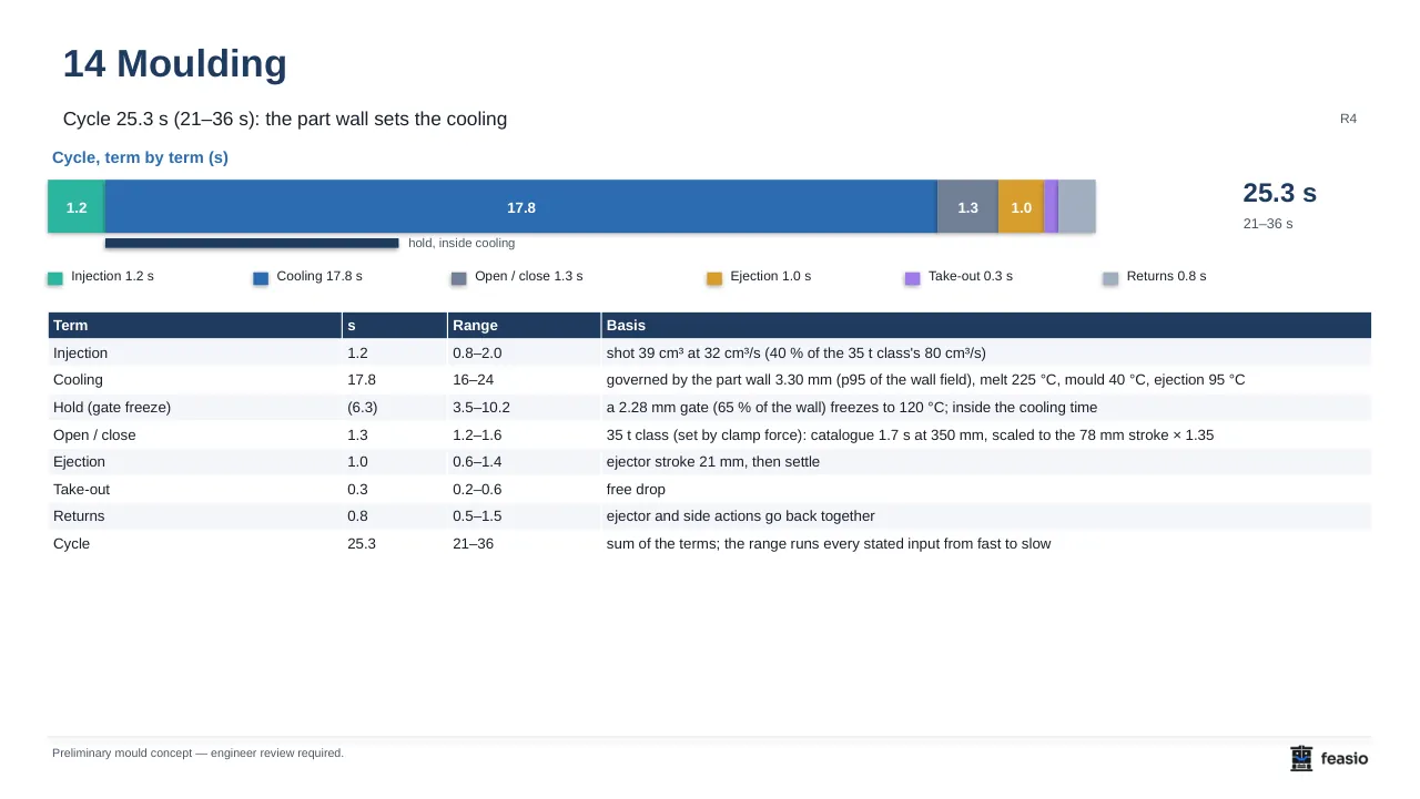
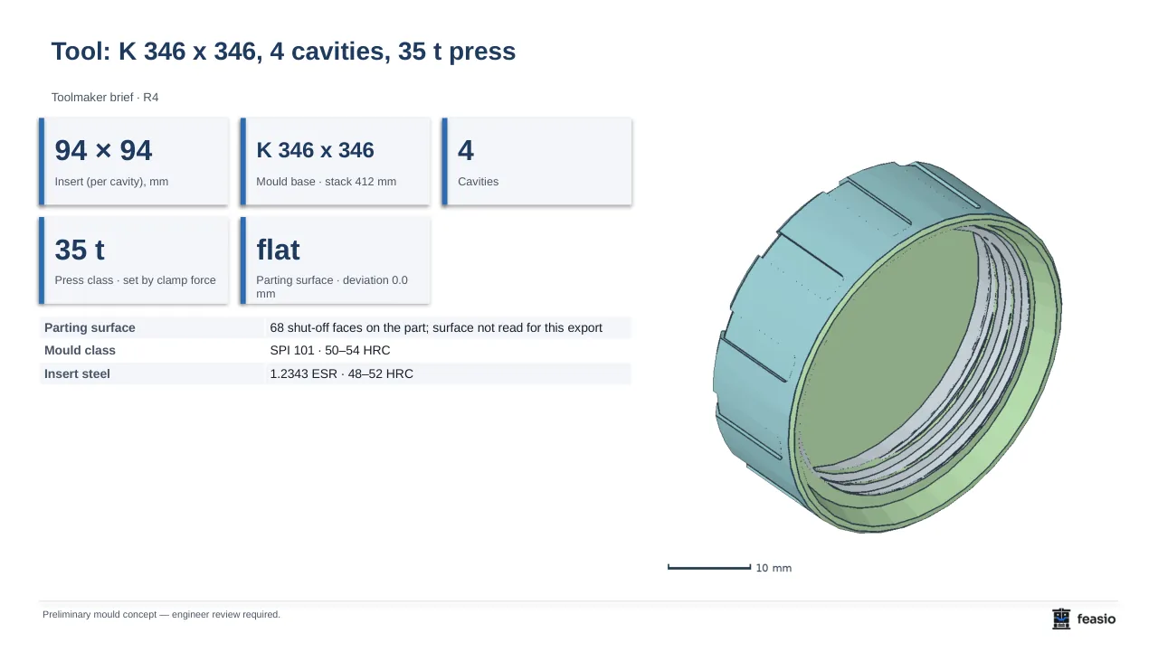
Pictures on this site show a shareware closure cap and publicly available scanned automotive parts. No customer geometry is shown, and part numbers have been removed.
Tolerance check on the customer drawing – ISO 20457
Feasio reads every toleranced dimension from the PDF drawing in minutes: the text layer, plus vision for scanned sheets and GD&T frames. Each one is judged against the material's own variation (shrinkage scatter, anisotropy, temperature) and the ISO 20457:2018 tolerance groups. The suspicious ones are circled in the toolmaker brief with the numbers.
- Example: PP scatters ±0.20 mm over 200 mm; the drawing asks ±0.02 mm.
- Flags metal general tolerances (ISO 2768) on a plastic part.
- Flags tight tolerances across the parting line.
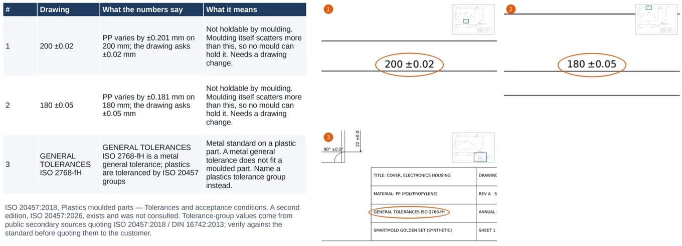
ISO 20457:2018, Plastics moulded parts — Tolerances and acceptance conditions.
What it works to, and where it stops
The report names the source of every value and what it does not cover. That is what lets an engineer put a signature under it.
How it decides
- Fast first, exact where it decides. Column scans and meshes rank the options; exact B-Rep geometry and mesh booleans confirm the chosen one.
- Grey where unsure. Where a wall value is uncertain the map shows grey instead of a plausible number.
- Same input, same answer. The measuring mesh is deterministic and every result carries its checksum.
- Geometry without a language model. The measurements and rules run without AI. The AI reads the same numbers at the decision points and its picks are labelled as such.
References
- SPI mould classes 101–105
- Tool class from the programme's cycle count.
- VDI 3400 texture
- Extra draft per texture grade on textured faces.
- Standard mould-base sizes
- The tool envelope set on standard plate sizes.
- Tool steels by W.-Nr.
- Steel and hardness per component, e.g. 1.2343 ESR at 48–52 HRC for inserts.
- Material data
- Shrinkage, draft and wall limits per material family.
What it does not do
- It is not a mould-flow simulation. Sink and hot cores are geometric screenings.
- It gives no tool price and no lead time.
- It does not produce production CAD of the inserts yet.
- It does not replace the tool designer's review and sign-off.
- It holds no security certification yet, such as ISO 27001 or TISAX.
Measured times
Time for the DFM analysis stage in our benchmark run of 2 October 2026, on a development laptop with a 4 GB NVIDIA GPU. Production runs on a server GPU; other hardware gives other times.
| Part | Material | DFM stage |
|---|---|---|
| Closure cap | PP | 57 s |
| PET preform | PET | 52 s |
| Automotive exterior part | PP | 91 s |
| Large automotive air guide | PP-TF20 | ≈ 9 min |
Wall thickness, tool interior and the reports are separate stages with their own times. Every stage logs its timing, so the pilot measures them on your parts.
Who it is for
Tool-shop owner
A concept to quote from on the day the RFQ arrives.
Tool designer
The routine first pass done, the decisions left with you.
Moulding-plant technical lead
DFM feedback for your customer before you commit to a price.
OEM or Tier-1 tooling engineer
One standard report for every supplier part.
The pilot: three months on the parts you are quoting now
Bring the RFQs on your desk, and one part you quoted last year and know the answer to. We set Feasio up with you, run the parts together and measure what it changes in your quoting.
Included
- Onboarding on your own parts, with us beside you
- The full feature set for 3 months
- A weekly call with the people who build Feasio
- Your material and draft rules set up in the product
- A real say in what is built next
Why three places
We work alongside every pilot team each week. Three is the number we can do that for properly.
3 places · Hungary first
Request a pilot place- We sign your NDA before the first part.
- Your parts are processed on our own servers and not shared with third parties.
Questions
Does Feasio replace the tool designer?
No. It produces a preliminary concept: the direction, the findings, the mechanisms and the tool envelope, each with its basis. Your engineer reviews every decision, and the report marks what was measured, what was assumed and what is waiting for review.
How far can I trust the numbers?
Every value carries its source and its unit. The options are ranked with fast scans, and the chosen direction is confirmed on the exact CAD geometry. Where a value is uncertain it is shown grey, never filled in. Estimates such as cycle time are given as ranges.
How long does one part take?
On our benchmark set the DFM stage takes about a minute for a closure cap and about nine minutes for a large automotive air guide. The whole chain to the report takes longer and depends on the part. The pilot measures it on yours.
My customers' CAD is confidential. Where does it go?
During the pilot your parts are processed on our own servers and are not shared with third parties. We sign your NDA. We do not hold a security certification such as ISO 27001 or TISAX yet.
Does it give the tool price?
No, on purpose. It gives what a quote is built from: SPI class, mould-base envelope, steels, mechanisms, cavity count, press size and a cycle range. The price stays with your own costing.
Is it a mould-flow simulation?
No. Sink, junctions and hot cores are screened geometrically against the material's limits, and the cycle time is an estimated range. Where filling or warpage matters, run your flow simulation; Feasio shows you where to look.
Which mechanisms does it handle?
Lifters, slides, core pulls, opposed lifter pairs (V-lifters), split cores, two-stage ejection, unscrewing cores, and stripping for elastomers such as TPU, TPE and LSR. Internal undercuts go to lifters, because a slide cannot reach inside the part.
Where does the AI come in?
At the decision points only. It reads the same measured numbers as the rules and gives its reading next to the recommendation; its picks are labelled. The geometry and the measurements run without a language model.
Why a limited pilot and not a free trial?
Because we set it up on your parts with you and meet every week, and three teams is what we can do that for properly.
Which languages are the reports in?
Hungarian and English, as a customer edition, an internal edition and a toolmaker brief, in PPTX and PDF. This site is also in German, Italian and Japanese; reports in those languages are not available yet.
Built with
Exact CAD geometry where the decision needs it, GPU computing where speed does.
- NVIDIA® CUDA® GPU computing for ray and column scans of the part.
- Open CASCADE Technology Exact B-Rep geometry: CAD import, ray casts on the surfaces, the release proof.
- Intel® Embree Ray tracing on the measuring mesh to rank opening directions.
- Manifold Exact mesh booleans for the tool interior: inserts, heads, pockets.
- PostgreSQL® Projects, decisions and their history.
- Python® Rules engine, measurements and the report generator.
- React and three.js The interface and the 3-D viewer.
- AMD Ryzen™ processors CPU compute for the geometry jobs.
- Cloudflare® Delivery of this site.
Product names identify the technology we use. They do not imply endorsement by, or partnership with, their owners.